T Slots Tolerance
When using our custom T-slotted aluminum extrusions, you simply insert a T-nut and fastener into the extrusion and tighten it to create a durable, strong and lightweight structure that is both functional and attractive. More about aluminum. Compatibility is a big deal, we know. That’s why we’ve made it a point to ensure all. A T-slot with size A=22 mm and tolerance H8 shall be designated as: Tolerances on pitches of T-slots shall be as given below: T-slot - IS 2013 - 22 H8 2. Bureau of Indian Standards BIS is a statutory institution established under the Bureau of Indim Standards Act, 1986 to promote harmonious development of the activities of standardization. Provides a T-slot framing system and resources in your hands to turn dreams into reality. It's easy to assemble and can be configured into endless custom solutions, from DIY project to industrial applications. 80/20 is versatile - from machine guards to robotic arms, racing simulators, and workstations, it is a product for individuals, industries, and businesses.
If you are designing a ramp for a dog to get onto and off from the couch or a bed, you may use plastic sections with slots to snap the sections together.
A slot in a plastic molded part may have draft. This complicates how it should be dimensioned. Below is a best practice for how to dimension slots with draft.
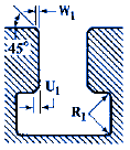
The figure below shows our slot. Not only does it have draft, but it also has fillets and rounds.
We start with the goal of locating the the slot with a tolerance of position. Recall that a tolerance of position must be applied to a feature of size. That's easy if the slot has no draft. But our slot has draft. So we cannot define the entire slot as a feature of size. We need to pick a specific place in our slot to define as our feature of size. The top and bottom of the slot are not good places to define a feature of size because the top and bottom have corners that may or may not be sharp. This is why we go down a basic distance, a basic 10 in this case, from the top of the slot. This is where we will define our feature of size. Our size dimension says that at exactly 10 down from datum [A], the size must be 20 +/- 0.2.
Having established a feature of size, we can locate our feature of size with a tolerance of position. Our tolerance of position says that the center of our feature of size must fall within a 0.5 wide tolerance zone while holding the part on datum feature [A], and pushing it against datum features [B] and [C]. The slot is oriented to datums [A] and [B] and located to datum [C].
Everything we have looked at so far is specifically 10 mm away from datum [A]. Now we need to define the rest of the walls. We use a profile of a surface with a 0.1 wide tolerance zone. The profile of a surface does not locate the walls. They are located by the tolerance of position and the size tolerance. The profile of a surface controls the orientation and form. The profile tolerance zone will float within the size tolerance zone, and the profile tolerance zone will be exactly 99.5 degrees to datum [A] and exactly perpendicular to datum [B].
Finally we control the location, orientation, and form of the bottom of the slot with a profile of a surface that has a 0.5 wide tolerance zone. The tolerance zone is located and oriented to datum [A].
The profile tolerance zones can float within the size tolerance zones. Each profile tolerance zone is independent of the other one. Each profile tolerance zone is two parallel planes 0.1 apart, exactly 99.5 degrees from [A] and exactly perpendicular to [B].


| Link | Semantic Value |
|---|---|
| Term | Slot Tolerance Window |
| Status | |
| Mandatory for | |
| Contexts | |
| Categories | |
| Synonyms | |
| Related entries | Departure Tolerance Window (DTW) |
| Broader term | |
| Narrower term |

Abbreviation
STW
Definition
Time window around the CTOT in which a flight should be taking off. By default 5 minutes before and 10 minutes after CTOT. This value can be updated in ETFMS.
Definition Source
EUROCONTROL, CFMU Glossary, Sept. 2011
Note
ETFMS uses a Slot Tolerance Window (STW) for regulated flights and a Departure Tolerance Window (DTW) for non regulated flights. These windows are used for the production of statistics and for the processing of DPI messages.
T Slot Tolerances
Note Source

EUROCONTROL (2011) CFMU, DPI Implementation Guide
T Slots Tolerance
